Wednesday, 29 August 2018

ORIENTATION OF PLANE TABLE


ORIENTATION

The method of setting up plane table at each of the successive stations parallel to the position it occupied at the starting station is known as orientation.
  Orientation must be done when the plane table is set up at more than one station. As already started, plane tabling is base on principle of parallelism. So, the relative position of the objects on the map will be accurate only if the orientation is proper. But orientation is not done, then the map will not represent the actual position of the objects.
  Orientation may be done by magnetic needle and back-sighting.

Orientation by magnetic needle: This method is suitable when the local attraction is not suspected in the area.

Procedure [a] Suppose A and B are two stations. The plane table is set up at station A and levelled by sprit level. The centring is done by U-fork and plumb bob so that the point a is just over station A. Then the tough compass or circular box compass is placed on the right-hand top corner of the sheet in such a way that the needle is coincides with ‘0-0’ mark. After this a line representing the north line is drawn through the edge of the compass box. The table is then clamped.

[b]. With the alidade touching the point a, the ranging rod at B is bisected and a ray is drawn. The distance AB is measured and plotted to any suitable scale.    

[c]. The table is shifted and centred over B, so that the point b is just over B. The table is levelled. Now the trough compass is placed exactly along the north line drawn previously. The table is then turn clockwise or anticlockwise until the needle coincides exactly with the 0-0 mark of the compass.
  While turning the table, care should be taken not to disturb the centring. In case it is, it should be adjusted immediately.

[d]. When centring and leveling are perfect and the needle is exactly at 0-0, the orientation is said to be perfect (Fig. 8)


Orientation by back-sighting: This method is accurate and is always preferred.

Procedure [a] Suppose A and B are two stations. The plane table is set up at station A and levelled by sprit level. The centring is done by U-fork and plumb bob so that the point a is just over station A. Then the tough compass or circular box compass is placed on the right-hand top corner of the sheet in such a way that the needle is coincides with ‘0-0’ mark. After this a line representing the north line is drawn through the edge of the compass box. The table is then clamped.

[b]. With the alidade touching the point a, the ranging rod at B is bisected and a ray is drawn. The distance AB is measured and plotted to any suitable scale.    

[c]. The table is shifted and centred over B, so that the point b is just over B. The table is levelled. Now the alidade is placed along the line ba, and the ranging rod at A is bisected by turning the table clockwise or anticlockwise. At this time the centring may be disturbed and should be adjusted immediately if required. When the centring, leveling and bisection of the ranging rod a A are perfected, then the orientation is said to be perfect (Fig. 9).


(Next post on “METHOD OF TABLING”)


Sunday, 26 August 2018

PLANE TABLE SURVEYING


PLANE TABLE SURVEYING

PRINCIPLE AND ACCESSORISES OF PLANE TABLE.

PRINCIPLE

  The principle of plane tabling is parallelism, meaning that the rays down from stations to subjects on the paper are parallel to the lines from the stations to the objects on the ground. The relative positions of the objects on the ground are represented by their plotted positions on the paper and lie on the respective rays.
  The table is always placed at each of the successive stations parallel to the position is occupied at the starting station. Plane tabling is graphical method of surveying. Here, the field work and plotting are done simultaneously, and such survey does not involve the used oh field book.
  Plane table survey is suitable for filling interior details when traversing is done by theodolite. Sometimes traversing by plane table may also be done. But this survey is recommended for the work where grate accuracy is not required. As the fitting and fixing arrangement of this instrument is not perfect, most accurate work can not be expected.  

ACCESSORISES OF PLANE TABLE.

1). Plane table: The plane table is a drawing board of size by 750 mm x 600 mm made of well-seasoned wood like teak, pine, etc. the top surface of the table is well leveled. The bottom surface consists of a threaded circular plate for fixing the table on the tripod stand by a wing nut.
  The plane table is meant for fixing drawing sheet over it. The positions of the objects are located on this sheet by drawing rays and plotting to any suitable scale (Fig. 1).


2). The alidade: There are two types of alidade – plain and telescopic.

a). Plain alidade. The plain alidade consists of a metal or wooden ruler of length about 50 cm. one of its edges is beveled and is known as the fiducial edge. It consists of two vanes at both ends which is hinged with the ruler. One is the known as the ‘object vane’ and carries a horse hair; the other is called ‘sight vane’ and is provided with a narrow slit (Fig. 2).  
  

Fig. 2 

b). Telescope alidade. The telescope alidade consists of a telescope meant for inclined sight or sighting distant objects clearly. This alidade has no vanes at the ends but is provided fiducial edge.
  The function of the alidade is to sight objects. The rays should be drawn along the fiducial edge (Fig. 3).


Fig. 3 

3). The sprit level: The sprit level is a small metal tube containing a small bubble of sprit. The bubble is visible on the top along a graduated glass tube.
  The sprit level is meant for leveling the plane table (Fig. 4).


Fig. 4 

4). The compass: There are two types of alidade – (a) the tough compass and (b) the circular box compass.

a). The Touch Compass. The tough compass is a rectangular box made of non-magnetic metal containing a magnetic needle pivoted at the centre. This compass consists a ‘0’ mark at both ends to locate the N-S direction (Fig. 5).


Fig. 5

b). The Circular Box Compass. It carries a pivoted magnetic needle at the centre. The circular box fitted on a square base plate (Fig. 6).
  Sometimes two bubble tubes are fixed at right angles to each other on the base plate.
  The compass is meant for making the north direction of the map.


Fig. 6

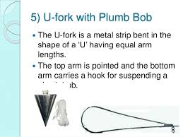
5). U-fork or plumbing fork with plumb bob: The U-fork is a metal strip bent in the shape of ‘U’ having equal arm lengths. The top arm is pointed, and bottom arm carries a hook for suspending a plumb bob (Fig. 7).
  This is meant for centering the table over a station.


Fig. 7 

(Next post on “ORIENTATION OF PLANE TABLE”)


Tuesday, 21 August 2018

CHECK ON CLOSED AND OPEN TRAVERSE FOR COMPASS SURVEYING


CHECK ON CLOSED AND OPEN TRAVERSE

CHECK ON CLOSED TRAVERS

1). Check on angular measurements.

a). The sum of measured interior angles should be equal to (2n-4) x 90⁰ where  n is the number of sides of the traverse.
b). The sum of measured exterior angles should be equal to (2n+4) x 90⁰.
c). The algebraic sum of the deflection angles should be equal to 360⁰.

Right hand deflections are considered positive and left-hand deflection negative.

2). Check on linear measurements.

a). A line should be once each of two different days (along opposite direction). Both measurement should tally.
b). Linear measurements should also be taken by stadia method. The measurements by chaining or by other method should tally.


CHECK ON OPEN TRAVERS

In open traverse, the measurements can not be checked directly. But some field measurements can be taken to check the accuracy of the work. The methods are discussed below.

a). Taking cut-off lines. Cut-off lines are taken between some intermediate stations of the open traverse. Suppose ABCDEFG represents an open traverse. Let AD and DG be the cut-off lines. The length and the magnetic of the cut-off lines are measured accurately. After plotting the traverse, the distances and bearings are noted from the map. These distances and bearings should tally with the actual records obtained from the field (Fig. 12)


b). Taking an auxiliary point. Suppose ABCDEF an open traverse. A permanent point P is selected on the side of it. The magnetic bearings of this point are taken from traverse stations A, B, C, D, etc. If the survey carried out accurately and so is the plotting, all the measured bearings of P when plotted should meet at the point P. The permanent point P is known as the ‘auxiliary point (Fig. 13)


(Next Post on “PLANE TABLE SURVEYING”.)


Monday, 20 August 2018

KERALA IS FACING ITS WORST FLOOD IN 100 YEARS. MORE THAN 300 PEOPLE HAVE LOST THEIR LIVES AND MORE THAN 2 LAKH PEOPLE HAVE BEEN DISPLACED.
TOTAL DAMAGE IS OVER 19,500,00,00,000 INR.

IT IS IMPORTANT THAT COMMON PEOPLE LIKE US HELP!
YOU CAN DONATE DIRECTLY TO THE CHIF MINISTER'S DISTRESS RELIF FOUND (CMDRF) THROUGH THE BANK ACCOUNT (GIVEN BELOW). WHATEVER AMOUNT POSSIBLE :

LINK
https://donation.cmdrf.kerala.gov.in/

THANK YOU 🙏

Sunday, 19 August 2018

METHODS OF TRAVERSING BY COMPASS


METHODS OF TRAVERSING

Traverse survey may be conducted by the following methods:

1). Chain traversing (by chain angles)
2). Compass traversing (by free needle)
3). Theodolite traversing (by fast needle) and
4). Plane table traversing (by plane table)

1). Chain traversing: Chain traversing is mainly conducted when it is nor possible to adopt triangulation. In this method the angles between adjacent sides are fixed by chain angles. The entire survey is conducted by chain and tape only and no angular measurements are taken. When it is not possible to form triangles, as, for example, in a pond, chain traversing is conducted, as shown in Fig. 11.a and 11.b.
  The formation of chain angles is explained below.


First method- Suppose a chain angle is to be formed to fixed direction of sides AB and AD. Tie stations T₁ and T₂ are fixed on lines AB and Ad. The distances AT₁, AT₂ and T₁T₂ are measured. Then the angle T₁AT₂ is said to be chain angle. So, the chain angle is fixed by the tie line T₁T₂ (Fig. 11.a).
    
Second method- Sometimes the chain angle is fixed by chord. Suppose the angles between lines AB and AC is to be fixed. Taking A as the centre and a radius equal to 15 metre, an arc intersecting the lines AB and AC at points P and Q, respectively, is drawn. The chord PQ is measured and bisected at R (Fig. 11.b).

Let Angle PAR = θ

Then Angle BAC = 2θ

Here, AP = AQ = 15 m

In triangle PAR,

Sinθ = PR/AP = 2PR/2AP = PQ/30

Θ = Sinˉ¹ PQ/30

  The angle θ can be calculated from the above equation, and the chain angle BAC can be determined accordingly.

2). Compass traversing: In this method, fore and back bearings of the traverse legs are measured by prismatic compass and the sides of the traverse by chain or tape. Then the observed bearings are verified and necessary corrections for local attractions are applied. In this method, closing error may occur when the traverse is plotted. This error is adjusted graphically by using ‘Bowdithc’s rule’ (which is describe in future post).

3). Theodolite traversing: In such traversing, the horizontal angles between the traverse legs are measured by theodolite. The lengths of the legs are measured by chain, or tape, or employing the stadia method or by digital instrument. The magnetic bearing of starting leg is measured by theodolite. Then the magnetic bearings of other sides are calculated. The independent coordinates of all traverse stations are then found out. This method is very accurate.

4). Plane table traversing: In this method, a plane table is set at every traverse stations in the clockwise or anticlockwise direction, and the circuit is finally closed. During traversing the sides of the traverse plotted according to any suitable scale. At the end of the work, any closing error which may occur is adjusted graphically.

(Next Post on “CHECK ON CLOSED AND OPEN TRAVERSE”.)


Friday, 17 August 2018

PRINCIPLE OF COMPASS SURVEYING


PRINCIPLE OF COMPASS SURVEYING

  The principle of compass surveying is traversing, which involves a series of connected lines. The magnetic bearings of the lines are measured by surveyor compass and the distances od the lines are measured by chain or tape. Such survey does not require the formation of a network of triangles.
  Interior details are located by taking offsets from main survey lines. Sometime subsidiary lines may be taken for locating these details.
  Compass surveying is recommended when:

a). A large area to be surveyed,
b). The course of a river or coast line to be surveyed and
c). The area is crowded with many details and triangulation is not possible.

  Compass surveying is not recommended for areas where local attraction is suspected due to the presence magnetic substances like steel structure, iron ore deposit, electric cable conveying current, and so on.
 
TRAVERSING

  As already started in the last section, surveying which involves a series of connected lines is known as traversing. The sides of the traverse are known as ‘traverse legs’.
  In traversing, the lengths of the lines are measured by chain or tape and the directions are fixed by compass or theodolite or by forming angles with chain and tape.
 A traverse may be two types- closed and open.

Closed traverse: When a series of connected lines forms a closed circuit, i.e. when the finishing point coincides with starting point of a survey, it is called a ‘closed traverse’. Here ABCDEA represents a closed traverse (Fig. 9). Closed traverse is suitable for survey of ponds, forests, estates, etc.


Open traverse: When a sequence of connected lines extends along a general direction and dose not return to the starting point, it is known as ‘open traverse’ or ‘unclosed traverse’ Here ABCDE represents an open traverse (Fig. 10).


(Next Post on “METHODS OF TRAVERSING”.)


Wednesday, 15 August 2018

THE EARTH'S MAGNETISM. —Dip of the Needle


Magnetic Declination: The horizontal angle between magnetic meridian and true meridian is known as ‘magnetic declination’.

  When north end of the magnetic needle is pointed towards the west side of the true meridian the term ‘Declination West’ (θ W) (Fig. 7.a).

  When north end of the magnetic needle is pointed towards the east side of the true meridian the term ‘Declination East’ (θ E) (Fig. 7.b).


Isogonic and agonic lines:
  The lines passing through zero declination is said to be the ‘aogonic’ line (Fig. 8).


Variation of Magnetic Declination: The magnetic declination at a place is not constant. It varies due to the following reasons:

a). Secular Variation: The magnetic meridian behaves like a pendulum with respect to the true meridian. After every 100 years or so; it swings from one direction to the opposite direction, and hence the declination varies. This variation is known as ‘secular variation’.

b). Annual Variation: The magnetic declination varies due to the rotation of the earth, with its axis inclined, in an elliptical path around the sun during the year. This variation is known as ‘annual variation’. The amount of variation is about 1 to 2 minutes.

c). Diurnal Variation: The magnetic declination varies due to the rotation of the earth, with its own axis in 24 hours. This variation is known as ‘diurnal variation’. The amount of variation is found to be about 3 to 12 minutes.

d). Irregular Variation: The magnetic declination is found to vary suddenly due to some natural causes, such as earthquake, volcanic eruptions and so on. This variation is known as ‘irregular variation’.

Dip of the magnetic needle: If a needle perfect balanced before magnetisations, it does not remain balanced position after it is magnetised. This is due to magnetic influence of earth. The needle is found to be inclined toward the pole. This inclination of the needle with the horizontal is known as ‘dip of the magnetic needle’.
  It is found that the north end of the needle is deflected downwards in the northern hemisphere and that its south end deflected downwards in the southern hemisphere. The needle is just horizontal at the equator. To balance dip of the needle, a rider (brass or silver coil) it provided along with it. The rider is placed over the needle at a suitable position to make it horizontal.

Local attraction: A magnetic needle indicates the north direction when freely suspended or pivoted. But the needle comes near some magnetic substances, such as iron ore, steel structure, electric cable conveying current: etc. it is found to be deflected from its true direction, and dose not show the actual north. This disturbing influence of magnetic substance is known as the ‘local attraction.    
  To detect the present of local attraction, the fore and back bearing of a line should be taken. If the difference fore and back bearings of the line is exactly 180⁰, then there is no local attraction.
  To compensate of local attraction, the amount of error found out and is equally distributed between fore and back bearings of the line.
  For example, consider a case when

Observed FB of line AB = 70⁰30’
Observed BB of line AB = 230⁰0’

Calculated BB of line AB = 70⁰30’ + 180⁰ = 250⁰30’
Corrected BB of line AB = ½ (230⁰0’+250⁰30’) =240⁰15’
Hence Corrected FB of line AB = 240⁰15’ -180⁰ = 60⁰15’

Method of application of correction

a). First method: The interion angles of a traverse are calculated from the observed bearings. Then an angular check is applied. The sum of interion angles should be equal to (2n-4) x 90⁰ (n being the number of sides of the traverse. If it is not so, total error equally distributed among all the angles of the traverse.
  Then starting from the unaffected line, the bearings of lines may be corrected by using the corrected interior angles. This method is very laborious and is not generally employed.

b). Second method: In this method interior angles are not calculated. From the given table, the unaffected line is first detected. Then, commencing from the unaffected line, the bearings of the other affected lines are connected by finding the amount of correction at each station.
  This is an easy method, and one which is generally employed.
  If the all lines of a traverse are found to be affected by local attraction, the line with minimum error is identified. The FB and BB of this line are adjusted by distributing the error equally. Then, starting from the this adjusted line, the fore and back bearings of other lines are corrected.
  

(Next Post on “PRINCIPLE OF COMPASS SURVEYING”.)


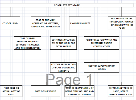
ESTIMATING

  ESTIMATING   What is an Estimate?       Before starting any work for it’s execution the owner or client or builder or contractor shoul...