Tuesday 31 July 2018

THE CHAIN TRAVERSE


THE CHAIN TRAVERSE.

  An irregular boundary or a winding road or stream may sometimes be traversed by chain alone, although a compass or theodolite traverse is usually preferable in cases where there is no alternative to a traverse of some kind.


  The method will be understood from fig. 28 and fig. 29, the bends in the lines being fixed by small triangles, of which the lengths of all three sides are measured.
  It will be seen from either of the above examples that a good deal of room is required at the bends in order to get in the extra tie lines or triangles. Hence, the method is not always possible, even when it is otherwise allowable, and the most satisfactory method of survey in such cases is normally an instrumental traverse, either using a compass to measure the directions of the lines, or a theodolite to measure the angles at the bends. The survey of a closed figure like that shown in fig. 29 can be strengthened by one or more tie lines across it, such as the line EC. The method is not sound in practice if any other is available, because the directions of long legs are determined by measurements of triangles with short sides, so that any small linear error in the measurement of the sides of a triangle will be magnified in the swing of the end of the leg whose direction is determined by the triangle.

Sunday 29 July 2018

OBSTACLES IN CHAINING


Obstacles in Chaining.

  Cases often occur in the field where the distance between two points is required, but direct chaining from one point to the other is impossible because of some sort of obstacle.
  There are two main cases to be considered: (1) obstacles which obstruct chaining but not ranging, (2) obstacles which obstruct both chaining and ranging, and, of those which come under (1), we may distinguish between (a) obstacles round which chaining is possible, and (6) obstacles round which it is not possible to chain.


  Case 1 (a). In fig. 25.a the line crosses a lake between A and B and the distance AB is required.
  At A and B range out lines AC and BD perpendicular to the chain line and make AC equal to BD in length. Then the line CD can be chained and will be parallel and equal in length to AB.
  Other alternative methods are shown in figs. 25.b, 25.c and 25.d.
  In fig. 25.b, E is the middle point of a chained line AC chosen so that the lines EA and EB clear the obstacle. Produce BE to D and make ED = BE. Then DC is equal and parallel to AB.
  In fig. 25.c, C is the middle point of AE and D the middle point of BE. Then AB = 2 x distance CD.
  In fig. 25.d, a perpendicular BC is dropped on a line AC and AC and BC are measured. Calculate from tan Ө = BC/AC, and AB from AB = AC sec Ө = BC cosec Ө.


  Case 1 (b). Here a wide river prevents chaining round the obstacle. In fig. 26.a, take a point C on line AB produced and erect perpendiculars to AB at C and B. Take point D on the perpendicular from C and line in E so as to be on the perpendicular from B and on the line DA. Measure BC, BE and CD. Then

AB/BE = BC/(CD – BE)    or AB = (BE X BC)/(CD – BE)

  In fig. 26.b, lay out and measure BC perpendicular to BA and mark the middle point E. At C lay out line CD perpendicular to BC and find point D on this perpendicular such that D, E and A are all in a straight line. Measure CD, which is equal to BA.
  In fig. 26.c, set out BC perpendicular to BA, and at C set out line CD at right angles to AC. Choose point D on this line so that D is in line with B and A. Measure BD and BC. Then

AB/BC = BC/BD and so AB = BC²/BD

  In fig. 26.d, choose a line AC which makes an angle of about 30⁰ with AB, and from B drop line BC perpendicular to AC. Measure CB and prolong CB to D so that BD = CB. At D lay out line DE at right angles to CBD and find the point E on this line which is in line with B and A. Measure BE, which is equal to BA.

  Case 2. Obstacles which prevent both chaining and ranging. In fig. 27.a, 27.b, 27.c, a building interferes with the direct ranging as well as with the chaining of the line AB.


  (1). In fig. 27.a, set out lines AC and BD perpendicular at A and B respectively to AB, and make AC = BD. From C set out points E and F on line CD, ahead of D and clear of the obstacle. At E and F set out lines EG and FH, equal in length to CA or DB and at right angles to CDEF. Measure DE. Then GH is a continuation of AB and BG = DE.
  (2). In fig. 27.b, choose a suitable point C, measure AC and BC and lay out points D and E on lines BC and AC, so that

CE/CA = CD/CB = k, say,

Set out points F and G in line with D and E and measure OF and CG. Produce CF and CG to I and H, making

CI/CF = CH/CG = CA/CE = 1/k

Measure EF. Then H and I are on BA produced and

AI = EF X CA/CE = 1/k X EF

  (3). In fig. 27.c, lay out line BE and measure BD and BE. Let BD = k X BE. Lay out line BF and line in point C at the intersection of BF and DA produced. Measure BC and make BF = 1/k x BC.
Measure DA and on line EF put in point G so that EG = 1/k X DA.
G is then a point on BA produced. Similarly, find another point L on BA produced. Measure BA.

Then       AG= BA{(1/k) – 1} and GL is a continuation of BA.


Friday 27 July 2018

How to Run a Line through a Given Point Parallel to a Chain Line.


To run a Line through a Given Point Parallel to a Chain Line.

  Let AB, fig. 22, be the chain line and C the point through which it is desired to lay out a line parallel to AB.
  From C lay out CD perpendicular to AB and measure the length of CD. Choose a point E on the line AB as far as possible from D and at E erect a perpendicular EF to AB equal in length to CD. The points C and F will then be on a straight line parallel to AB.


  An alternative method is to choose points D and E, fig. 23, suitably placed on the line AB and measure the distance CD, leaving arrows at every chain length near the point which appears to be the centre of the line. Having obtained the length of CD, use the arrows to put a mark at F so that CF = FD. Measure the distance EF and prolong the line to G so that FG = EF. Then the line CG is parallel to AB.


  In the above case the point C is supposed to be accessible. If it is inaccessible, as in fig. 24, establish the foot D of the perpendicular CD on the line AB by the method described on previous tropic and obtain the distance DC by one of the methods described on next. A point F on the line CF can now be obtained by laying out EF perpendicular to AB and making EF equal in length to DC.

Wednesday 25 July 2018

How to Drop a Perpendicular from a Given Point to a Given Straight Line.

To drop a Perpendicular from a Given Point to a Given Straight Line.


  Let it be required to lay out a line perpendicular to the line AB
from a given point C (Fig. 20). Fasten the end of the chain at C, or get a chainman to hold it there, and choose some convenient length CD to form one side of an isosceles triangle CDE. Get an assistant to hold the graduation mark on the chain at D and, standing at G a short distance behind A, signal
to him to move the tightened chain until D appears to be in line with AB and get him to put in an arrow. Have a similar arrow put in at E, where CE = CD and E is on the line AB. Measure the distance DE and put in an arrow at F on the line AB such that DF = ½DE. The line FC is then at right angles to AB and passes through C.


  If the point C is inaccessible, as in Fig. 21, choose suitable points D and E on the line AB and from D and E lay out lines DF and EG perpendicular to EC and DC respectively.
  Then line out a point H so that it lies on the intersection of the lines DF and EG. Finally, from H lay out HK perpendicular to AB. The line KH when produced should then pass through C, as should be verified by standing


behind a pole at K and seeing if K, H and C are on one straight line.

Monday 23 July 2018

How to Lay Out a Right Angle from a Point on a Chain Line.

To Lay Out a Right Angle from a Point on a Chain Line.

The operations to be considered in the next few pages are all based on simple geometrical propositions and are the equivalent on the ground of easy problems in geometrical drawing.

  Let AB, (Fig. 18), be a chain line, and let it be required to lay out a line from a point C on AB at right angles to AB.
  If an optical square is available, stand at C and, viewing a ranging pole at A or B directly through the square, signal to a man holding a ranging pole at D until the image of the latter in the instrument appears to coincide with the pole seen directly through the aperture in the square.
  If no optical square is available, the work can be done with the chain alone, although neither of the two methods to be described is as convenient as using an optical square. The principle of the first method depends on the well-known fact that, in a right-angled triangle, the sum of the squares on the two sides containing the right angle is equal to the square on the hypotenuse. Thus, with sides of 3, 4 and 5, we have 3² + 4² = 5², the sides of lengths 3 and 4 containing the right angle, and the side of length 5 being the hypotenuse.


Standing at C, lay out a point E in line with A so that the distance CE measures 4 units, and put arrows in the ground at E and C. Fastening one end of the chain at C, or getting an assistant to hold it there, get an assistant to hold the graduation 8 at E. Hold the chain at graduation 3 and move to the side of the line towards which the right angle is to be laid out until the two lengths of the chain are taut at some point D. Place an arrow at D. D is then a point on a line at right angles at C to the line AB, as the sides of the triangle ECD are equal to 5, 4 and 3, as shown in the diagram.
  Instead of taking short lengths of 5, 4 and 3, it is generally better

Another method is to lay out two equal distances CE and CF, to use a multiple of these figures. Thus, EC could be made 40 links, DC 30 links, and DE 50 links. each about 40 links long, on either side of C and both on the line AB (Fig. 19). Then, if the ends of the chain are held at E and F, an arrow is held at the centre of the chain, and the two lengths pulled equally taut, the arrow will be at a point G such that GC is at right angles
to AB.


  Any of the above described methods is good enough for ordinary chain survey work, but cases sometimes occur where the work will not be sufficiently accurate unless it is done with a theodolite. In this case, set up the instrument at C, sight on A or B, and lay off an angle of 90 on the horizontal circle. The line of collimation will then be perpendicular to AB.


www.youtube.com/watch?v=69cslx6ER7k&t=1s


Saturday 21 July 2018

RANGING STRAIGHT LINES


Ranging Straight Lines.

Ranging a line means establishing a set of intermediate points on a straight line between two points already fixed on the ground. The simplest case occurs when the two points are intervisible and a start is made from one end of the line. Let A and B, (Fig. 13), be the two points between which it is necessary to establish a number of intermediate points. Having set up vertical ranging poles at A and B, move a short distance behind the point B, the point from which it is proposed to work, to a point C, so that on looking towards A the ranging poles at A and B appear to be in a straight line with the eye.


Standing at C, get an assistant to hold a pole near some intermediate point d, and, using suitable signals or shouts, get him to move his pole right or left of the line until A, d and B, all appear to be in a straight line. If required, points g and h beyond A can be lined in in a similar manner.

The assistant should be made to stand to one side of the line during these operations, so that his body does not obstruct the sight to the distant point. He must also hold his ranging pole vertical by supporting it loosely between the forefinger and thumb so that it tends to hang vertical under its own weight.


Sometimes the whole of the intermediate line cannot be seen from the ends. In fig. 14 there is a gulley between A and B, and neither point can be seen from points inside the gulley. Establish points d and e on the line between A and B on the edges of the gulley and mark them by ranging poles. Then move to d and from behind d line in a pole at f on the straight line between d and e and possibly another pole at g between f and e. If necessary, move to f and put in intermediate poles at h and i. In this way, the line can easily be laid out over the gulley.

Another case arises when the ends of the line are not intervisible. This problem can easily be solved when a theodolite is available by making a survey of the relative positions of the two ends and calculating a bearing between them which can be laid out on the ground. In heavy bush country, where heavy clearing is involved, this is the easiest method, even if lines have to be specially cut for the legs of a preliminary traverse. For many purposes, however, such an elaborate procedure is not necessary, and a line can be established by ranging pole alone or by ranging pole and chain.


In fig. 15 a hill intervenes between A and B, so that these points are not intervisible. If a point C on the hill can be chosen such that it views A and B, it can be ranged in by a line ranger or by the method now to be described. Intermediate points between A and C and between C and B can then be ranged in in the ordinary way.


Choose the point C which, as closely as can be judged by eye, is on, or very close to, the line AB and line in a point D between A and C. On going to D, (Fig. 16) stand behind the pole there and look in the direction of B. In all probability it will be seen that D, C and B are not in a straight line. From D line in a point E between D and B. Proceed to E and from a point behind it see if E, D and A are on line. If not, line in the point F on the line EA. Proceeding in this way, keep moving the poles closer and closer to AB until, after a few trials, they are seen to lie on it.


If, as in fig. 17, it is not possible to choose a point between A and B from which both, points can be seen, estimate the direction of A from B as closely as possible, and range and chain a straight-line BD in that direction, leaving intermediate numbered pegs along BD at the end of each chain length. From A lay out a line AE perpendicular to BD at E and measure the length of AE and the chainage of E. Then, points such as f can be found by drawing a perpendicular to BE at F and laying out Ff such that

 Ff = EA x BF/BE


Friday 20 July 2018

OFFSET IN CHAIN SURVEY

Offset
The lateral measurement taken from an object to the chain line is known as ‘offset’. Offsets are taken to locate objects with reference to the chain line. They may be of two kinds. 
1. Perpendicular offset and
2. Oblique offset.

Perpendicular offset: When the lateral measurements are taken perpendicular to the chain line, they are known as perpendicular offsets (Fig. 10


Perpendicular offsets may taken in the following ways.


    1. By setting a perpendicular by swinging a tape from the object to the chain       line. The point of minimum reading on the tape will be the base of the             perpendicular (Fig. 11.a)
.       2. By setting a right angle in the ratio 3:4:5 or 5:12:13 (Fig. 11.b)
    3. By setting a right angle with the help of builder’s square or tri-square (Fig. 11.c)
      4. By setting a right angle by cross-staff or optical square.
Perpendicular offset are preferred for the following reasons:
(i)                  The can be taken very quickly.
(ii)                 The progress of survey is not hampered.
(iii)                The entry in the field book becomes easy.
(iv)               The plotting of the offsets also becomes easy.


Oblique offset: Any offset not perpendicular to the chain line is said to be oblique offset. Oblique offset taken when the objects are at the long distance from the chain line or when it is not possible to set up a right angle.

Oblique offsets are taken in the following manner.


Suppose AB is a chain line and p is the corner of a building. Two points ‘a’ and ‘b’ are taken on the chain line. The chain ages of ‘a’ and ‘b’ are noted. The distance ‘ap’ and ‘bp’ are measured and noted in the field book. Then ‘ap’ and ‘bp’ are the oblique offsets (Fig. 12). When the triangle ‘abp’ is plotted, the apex point ‘p’ will represent the position of the corner of the building.


www.youtube.com/watch?v=v8HpoVHBhho&t=300s


Wednesday 18 July 2018

SURVEY STATIONS

 SURVEY STATIONS

Survey stations are the points at the beginning and the end of a chain line. They may also occur at any convenient points on the chain line. Such station may be:
 1.   Main stations.
 2.   Subsidiary stations. And
 3.   Tie stations.


Main Stations.

Which stations taken along the boundary of an area as controlling points are known as ‘main stations’. The lines joining the main stations are called ‘main survey lines’. The main survey lines should cover the whole area to be surveyed. The main stations are denoted by (Reff. Fig. 8.a) with letters A, B, C, D, etc. The chain lines are denoted by (Reff. Fig. 8.b).

Subsidiary Stations.
Which stations are on the main survey lines or any other survey lines are known as “subsidiary station”. These stations are taken to run subsidiary lines for dividing the area into triangles, for checking the accuracy of triangles and for locating interior details. These stations are denoted by (Reff. Fig. 8.c) with letters S1, S2, S3, etc.

Tie Stations.
Tie stations are also subsidiary stations taken on the main survey lines. Lines joining the tie stations are called tie lines. Tie lines are mainly taken to fix the directions of the adjacent sides of the chain survey map. These are also taken to form ‘chain angles’ in chain traversing, when triangulation is not possible. Sometimes tie lines are taken to locate interior details. Tie stations are denoted by (Reff. Fig. 8.d) with letters T1, T2, T3, etc.


Base Line.
The line on which the framework of survey is built is known as the ‘base line’. It is most important line of the survey. The longest of the main survey lines is considered the base line. This line should be taken through fairly level ground, and should be measured very carefully and accurately. The magnetic bearing of base line are taken to fix the north line of the map.

Check Line.


Which line joining the apex points of triangle to some fixed point on its base is known as the ‘check line’. It is taken to check the accuracy of the triangle.

Monday 16 July 2018

CHAIN SURVEYING


CHAIN SURVEYING

  PRINCIPLE 0F CHAIN SURVEYING

The principle of chain surveying is triangulation must. The area to be surveyed is divided into a number of small triangles which should be well conditioned. In this surveying the sides of the triangles are measured directly on the field by chain or tape, and no angular measurements are taken. Here the tie lines and check lines control the accuracy of work.
  It should be noted that plotting triangles requires no angular measurements to be made, if the three sides are known.


www.youtube.com/watch?v=uCa9wibnZCM


WELL CONDITIONED AND ILL CONDITIONED TRIANGLES 


When no angle in it is less than 30° or greater than 120° is said well-conditioned triangle (Fig. 7.a). An equilateral triangle is ideal triangle (Fig. 7.b). Well-conditioned triangles are preferred because their apex points are very sharp and can be located by a single ‘dot’. There are no possibility of relative displacement of the plotted point.
  A triangle in which an angle is less than 30° or more than 120° is said to be ill-conditioned (Fig. 7.c). Ill-conditioned triangles are not used in chain surveying because their apex points are not sharp and well defined, which is why a slight displacement of these point may cause considerable error in plotting.


Saturday 14 July 2018

COMMON SOURCES OF ERROR IN MEASUREMENT OF LINES.

COMMON SOURCES OF ERROR IN MEASUREMENT OF LINES.

1. Not pulling tape taut.
2. Careless plumbing.
3- Incorrect alignment.
4. Effect of wind.
5. Variation in temperature.
6. Erroneous length of tape.

COMMON MISTAKES IN READING AND RECORDING MEASUREMENTS.

1.   Failure to observe the position of the zero point of the tape. (In some tapes it is not at the end of the ring.)

2.   Omitting a whole chain- or tape-length.
3.   Reading from wrong end of chain, as 40 metre. for 60 metre., or in
         the wrong direction from a tag, as 47 metre. for 53 metre.
4.   Transposing figures, e.g., 46.24 for 4642 (mental); or reading
         tape upside down, e.g., 6 for 9, or 86 for 98
5.   Reading wrong foot-mark, as 48.92 for 47.92.

AVOIDING MISTAKES. — Mistakes in counting the tape lengths may be avoided if more than one person keeps the tally. Mistakes of reading the wrong foot-mark may be avoided by noting not only the foot-mark preceding, but also the next following foot-mark, as, "46.84 ... 47 metre," and also by holding the tape so that the numbers are right side up when being read.
  In calling off distances to the note keeper, the tapeman should be systematic and always call them distinctly and in such terms that they cannot be mistaken. As an instance of how mistakes of this kind occur, suppose a tape man calls, "Forty nine, three"; it can easily be mistaken for "Forty-nine metre." The note keeper should repeat the distances aloud so that the tapeman may know that they were correctly understood. It is frequently useful in doubtful cases for the note keeper to use different words in answering, which will remove possible ambiguity. For example, if the tapeman calls, "Thirty-six, five," the note keeper might answer, "Thirty-six and a half." If the tapeman had meant 36.05 the mistake would be noticed.
The tapeman should have called in such a case, "Thirty-six naught five." The following is a set of readings which will be easily misinterpreted unless extreme care is taken in calling them off.
47.0 — "Forty seven naught."
40.7 — "Forty and seven."
40.07 — "Forty, — naught seven."
'All of these might be carelessly called off, "Forty-seven."
 In all cases the tapemen should make mental estimates of the distances when measuring, in order to avoid large and absurd mistakes.

Accuracy Required. — If, in a survey, it is allowable to make an error of one metre in every five hundred metre the chain is sufficiently accurate for the work. To reach an accuracy of 1 in 1000 or greater with a chain it is necessary to give careful attention to the pull, the plumbing, and the deviation from the standard length. With the steel tape an accuracy of 1 in 5000 can be obtained without difficulty if ordinary care is used in plumbing and aligning, and if an allowance is made for any considerable error in the length of the tape. For accuracy greater than about 1 in 10,000 it is necessary to know definitely the temperature and the tension at which the tape is of standard length and to make allowance for any considerable variation from these values. While the actual deviation from the IS Standard
under certain conditions may be 1 in 10,000, still a series of measurements of a line all taken under similar conditions may check themselves with far greater precision.

Amount of Different Errors. The surveyor should have a clear idea of the effects of the different errors on his results. For very precise work they should be accurately determined, but for ordinary work it is sufficient to know approximately the amount of each of them. A general idea of the effect of these errors will be shown by the following.

Pull. - At the tension ordinarily used the light steel tape will stretch between o.o1 and 0.02 metre in 100 metre if the pull is increased 10 kg. Since the amount of stretch is different, however, for different tapes it is advisable to investigate it by fastening the ring of the tape to a nail in the floor and, with the tape lying flat, applying different tensions. The tensions should be measured with a spring balance and the variations in length under these different tensions may be determined from the tape readings of some reference point marked on the floor near the 100 metre end of the tape. In this manner the length of any particular tape for any given tension may be found.

Temperature. — The average coefficient of expansion for a steel tape is nearly 0.0000063 for 1° F. Hence a change of temperature of 15° produces nearly o.o1 metre change in the length of the tape. Tapes are usually manufactured to be of standard length at 62° F. and under a tension of 12 kgf. while supported throughout their length. When great accuracy is demanded the temperature of the tape must be determined and the corresponding temperature correction applied to the measurements.
Small tape thermometers are made especially for this purpose. The thermometer bulb should be in contact with the tape so as to obtain as nearly as possible the temperature of the steel. Even under these conditions it is difficult to determine the true temperature if the tape is exposed to sunlight.

Alignment. — The error in length due to poor alignment can be calculated from the approximate formula.

  c - a = h²/2xc

where h is the distance of the end of the tape from the line, c is the length of the tape, and a is the distance along the straight line. For example, if one end of a 50 metre tape is held 1 metre to one side of the line the error produced in this tape-length will be

 1²/2x50 = 0.01 metre (about 10 mm).

The correction to be applied to the distance when the two ends of the tape are not at the same level, as when making slope measurements, is computed in the same way.

Sag. — If a tape is suspended only at the ends it will hang in a curve which is known as the "catenary." On account of this curvature the distance between the end points is evidently less than the length of the tape. The amount of this shortening, called the effect of sag, depends upon the weight of the tape, the' distance between the points of suspension, and the pull exerted at the ends of the tape. With a 12 kg. pull on an ordinary
50 metre steel tape supported at the ends the effect of sag is from 0.01 metre to 0.02 metre. The most practical way to eliminate the effect of sag, however, is to determine by actual test the length between the end marks of the suspended tape as follows:


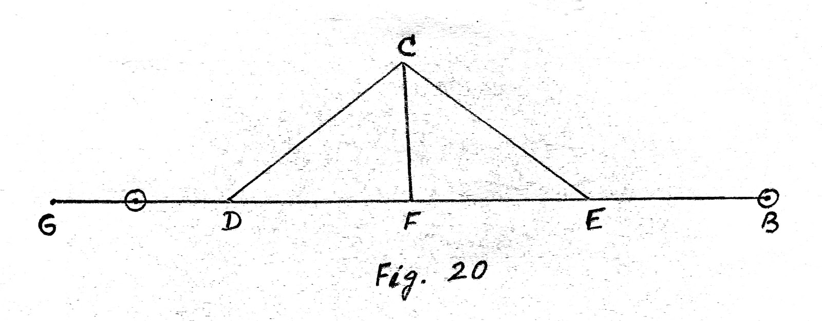
In the right triangle,


c² - a² = h²
(c-a)(c+a) = h²

Assuming c = a and applying it to the first parenthesis only,
2c (c-a) = h² (approximately)
c - a = h²/2c (approximately)

Similarly c - a = h²/2a (approximately)

It is evident that the smaller h is in comparison with the other two sides the more exact will be the results obtained by this formula. This formula is correct to the nearest 1/100 metre , even when h = 14 metre and a = 100 metre, or when h = 30 metre and a = 300 metre.
  First, while the tape is supported its whole length mark is end points while a pull of 12 kg is exerted. Then establish two points, by means of the transit or a plumb-line, at the same distance apart, but in such positions that the tape may be tested while supported at the ends only. Then determine the pull necessary to bring the end marks of the suspended tape to coincide with these reference marks. If this tension is always applied then the two ends of the suspended tape will be the same distance apart as the ends of the supported tape were under a 12 kg pull. If the supported tape is not of standard length when a 12 kg pull is used this error should be allowed for in all measurements. Or, if preferred, the reference marks just mentioned may be placed exactly 30 metre apart and the amount of pull required to make the suspended tape correct may be determined.

ACCURACY OF MEASURMENTS. - In surveying we are dealing entirely with measurements. Since absolute accuracy can never be attained, we are forced to make a careful study of the errors of measurement. Extremely accurate measurements are expensive, and the cost of making the survey usually limits its accuracy. On the other hand, if a given degree of accuracy is required, the surveyor must endeavor to do the work at a minimum cost. In most surveys certain measurements are far more important than others and should therefore be taken with more care than the relatively unimportant measurements. The surveyor should distinguish carefully between errors which are of such a nature that they tend to balance each other and those which continually accumulate. The latter are by far the more serious. Suppose that a line 1500 metre long is measured with a steel tape which is 0.01 metre too long and that the error in measuring a tape-length is, say, 0.02 metre, which may of course be a + or a - error. There will then be 50 tape-lengths in the 1500 metre line. A study of the laws governing the distribution of accidental errors (Method of Least Squares) shows that in such a case as this the number of errors that will probably remain uncompensated is the square root of the total number of opportunities for error, i.e., in the long run this would be true. Hence the total number of such uncompensated errors in the line is 7;

ESTIMATING

  ESTIMATING   What is an Estimate?       Before starting any work for it’s execution the owner or client or builder or contractor shoul...