Saturday 11 September 2021

COMPUTATION OF AREA AND VOLUME


COMPUTATION OF AREA AND VOLUME


AREAS

The method of computation of area depends upon the shape of the boundary of the tract and accuracy required. The area of the tract of the land is computed from its plan which may be enclosed by straight, irregular or combination of straight and irregular boundaries. When the boundaries

are straight the area is determined by subdividing the plan into simple geometrical figures such as triangles, rectangles, trapezoids, etc. For irregular boundaries, they are replaced by short straight boundaries, and the area is computed using approximate methods or Planimeter when the boundaries are very irregular. Standard expressions as given below are available for the areas of straight figures.


Area of triangle = ½absinθ

 Where   θ is the included angle between the sides a and b.

                          Or       

Area of triangle = √{s(s-a)(s-b)(s-c)}

 Where   a, b and c are the sides,

 And         s = ½(a+b+c)

                       Or

Area of triangle = ½ x b x h

 Where   b = base and h = altitude.

 Area of a rectangle = a x b

 Where    a and b are the sides.

 Area of trapezium = ½ x (a+b) x h

 Where  a and b are the parallel sides separated by perpendicular distance h.

 Various methods of determining area are discussed below.


Area Enclosed by Irregular Boundaries

 Two fundamental rules exist for the determination of areas of irregular figures as shown in Fig A.1. These rules are (i) Trapezoidal rule and (ii) Simpson's rule.


Trapezoidal Rule

In trapezoidal rule, the area is divided into a number of trapezoids, boundaries being assumed to be straight between pairs of offsets. The area of each trapezoid is determined and added together to derive the whole area. If there are n offsets at equal interval of d then the total area is


A = d( O₁+On + O+ O₃ + ......... + On-)

              2

 While using the trapezoidal rule, the end ordinates must be considered even they happen to be zero.


Simpson's Rule

In Simpson's rule it is assumed that the irregular boundary is made up of parabolic arcs. The areas of the successive pairs of intercepts are added together to get the total area.

A = d[(O₁+On) + 4(O+O₄+.......+ On-₂) + 2(O₃+O₅+....... + On-₁)]

       3

   = Common Distance[(1st Ordinate+Last Ordinate)+4(Sum of Even Ordinate)

                  3

                            +2(Sum of Odd Ordinates)]


Since pairs of intercepts are taken, it will be evident that the number of intercepts n is even. If n is odd then the first or last intercept is treated as a trapezoid.


Coordinate Method of Finding Area.

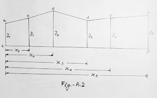
 When the offsets are taken at very irregular intervals, then the application of the trapezoidal rule and Simpson’s rule is very difficult. In such a case, the coordinate method is appropriate.

Procedure

From the given distances and offsets, appoint is selected as the origin in Fig A.2.


Taking h as the origin, the coordinates of all other points are arranged as follows.


   Points

         Coordinates

         X

          Y

      a

         0

          y₀

      b

         x₁

          y₁

      c

         x₂

          y₂

      d

         x₃

          y₃

      e

         x₄

          y₄

      f

         x₅

          y₅

      g

         x₅

          0

      h

         0

          0

      a

         0

          y₀


The coordinates are arranged in determinant form as follows.


Sum of products along the solid line,

 ∑P = (y₀x₁ + y₁x₂ + y₂x₃ + y₃x₄ + y₄x₅ + y₅x₅ + 0.0 + 0.0)

 Sum of products along the dotted line,

 ∑Q = (0.y₁ + x₁y₂ + x₂y₃ + x₃y₄ + x₄y₅ + x₅.0 + x₅.0 + y₀.0)

 Required area = ½(∑P-∑Q)


Planimeter

An integrating device, the planimeter, is used for the direct measurement of area of all shapes, regular or irregular, with a high degree of accuracy.

The area of plan is calculated from the following formula when using Amsler polar planimeter.

A = M(R₂ - R₁ ±10N + C)

 Where  

M = the multiplying constant of the instrument. Its value is marked on the   tracing arm of the instrument,

 R₁ and R₂ = the initial and final readings,

 N = the number of complete revolutions of the dial taken positive when the zero mark passes the index mark in a clockwise direction and 'negative’ when in counterclockwise direction, and

 C = the constant of the instrument marked on the instrument arm just above the scale divisions. Its value is taken as zero when the needle point is kept outside the area. For the needle point inside, -the value of MC is equal to the area of zero circle.


(Next post on “COMPUTATION OF VOLUME”)


Saturday 4 September 2021

DIFFICULTIES FACED IN LEVELLING


Difficulties faced in levelling.


[1]. When staff is too near the instrument: If the levelling staff is held very near the levelling instrument, the graduation of the staff are not visible. In such a case, a piece of white paper moved up and down along the staff until the edge of the paper is bisected by the line of collimation. Then the reading is noted from the staff with naked eye. Sometime the reading is taken by looking through the object glass.


[2]. Levelling across a large pond or lake: Suppose the levelling is to be done across a very wide pond or lake.

   We know that the water surface of a still lake or pond is considered to be level. Therefore, all points on a water surface have the same RL. Two pegs A and B are fixed on opposite banks of the lake or pond. The top of the pegs are just flush with water surface. The level is set up at O₁ and the RL of A is determined by taking an FS on A. The RL of B is assumed to the equal to of A. Now the level is shifted and set up at O₂. Then by taking a BS on peg B, levelling is continued (Fig.-L.26).     


[3]. Levelling across a river: In case of following water, the surface cannot be considered level. The water levels on the opposite edges will be different. in such a case, the method of reciprocal levelling is adopted. Two pegs A and B are driven on the opposite bank of the river (not flush with the water surface). The RL of A is determined in the usual way. Then the true difference of level between A and B is found by reciprocal levelling. Thus the RL of B is calculated, and levelling is continued.


[4]. Levelling across a solid wall: When levelling is to be done across a solid wall, two pegs A and B are driven on either side of the wall, just touching it. The level is set up at O₁ and a staff reading is taken on A. Let the reading be AC. Then the height of the wall is measured by staff. Let the height be AE. HI is found out by taking a BS on any BM or CP.


Then         RL of A = HI – AC

                 RL of E = RL of A + AE = RL of F  (same level)


   The level is shifted and set up at O₂. The staff reading BD is noted and the height of BF is measured.


Then          RL of B = RL of F – BF

                 HI at O₂ = RL of B + BD


   The leveling is then continued by working out the HI of setting (Fig.-L.27). 


[5]. When the BM is above line of collimation: This happens when the BM is at the bottom of a bridge girder or on the bottom surface of a culvert. It also happens when the RLS of points above the line of collimation have to be found out.

   Suppose the BM exists on the bottom surface of a culvert, and it is required to find out the RL of A. The level is set up at O and is held inverted on the BM. The staff reading is taken and noted with a negative sign. The remark “staff held inverted” should be entered in the appropriate column. Let the BS and FS readings be -1.45 and 2.30 respectively (Fig.-L.28).       


Now,          height of instrument = 100.00 – 1.45 = 98.55

                 RL of A = 98.55 – 2.30 = 96.25


[6]. Levelling along a steep slope: While levelling along a steep slope in a hilly area, it is very difficult to have equal BS and FS distance. In such case, the level should be set up along a zig-zag path so the BS and FS distance may be kept equal. Let AB the direction of levelling. I₁, I₂, …… are the position of the level and S₁, S₂, S₃, … the position of staff (Fig.-L.29).         


[7]. Levelling across a rising ground or depression: While a levelling across high ground, the level should not be place on top of the high ground but on the side so that the line of collimation just passes through the apex.

   While a levelling across depression, the level should be place on the side and not at the bottom of the depression (Fig. – L.30.a and L.30.b).


 Permissible error in levelling

   The precision of levelling ascertained according to the error of closure. The permissible limit of closing error depends upon the nature of the work for which the levelling is to be done. The permissible closing error is expressed as


            E = C√D 

Where,  E = closing error in metres

            C = the constant, and

           D = distance in kilometres.


The following are the permissible error of different type of levelling:


[1]. Rough levelling      E = ±0.100√D

[2]. Ordinary levelling   E = ±0.025√D

[3]. Accurate levelling   E = ±0.012√D

[4]. Precies levelling     E = ±0.006√D


Determination of Stadia Constant

   From the theory of the telescope it is known that


D = (f/i) x S + (f + d)


Where,   D = distance between vertical axis of the telescope and staff.

              f = focal length of object glass.

              i = length of image.

              S = difference of reading between the lower and upper stadia, and

              d = distance between optical centre and vertical axis of telescope.


   The quantity of (f/i) is known as the multiplying constant and its value is usually 100. The quantity (f + d) is called the additive constant and its value is normally zero. But sometimes its value lies between 20 and 30 cm.

   The values of constants are obtained by computation from field measurements.


Procedure:-  


[1]. A line OA, about 250 m long, is measured on level ground.

[2]. Pegs are fixed along this line at a known interval, say 25 m (Fig.-L.31).

[3]. The instrument is set up at O and stadia hair readings are taken at each

      of the pegs.

[4]. Thus the value of D and S are known for each of the pegs.

[5]. Putting these value of D and S in equation,


       D = (f/i) x S + (f + d)


   We get a numbers of equations.


[6]. The equations are solved in pairs to get several values of (f/i) and

       (f+d). The means of this values is taken as a stadia constant of the

       corresponding instrument.


Example: The following field observations are made with a level.


Distance in metre    Lower stadia    Upper stadia

          250.00                1.445              3.945

          225.00                0.930              3.180


Let us find the multiplying and additive constant.


Solution: We know that


              D = (f/i) x S + (f + d)


Let          (f/i) = x      and     (f + d) = y


                D = xS + y        ………………………..(1)


Substituting the observed values in (1), we get


                 250 = (3.945 – 1.445)x + y

                        = 2.50x + y           …………(2)


                 225 = (3.180 – 0.930)x + y  

                      = 2.25x + y           …………(3)


Subtracting Equation (3) from Equation (2)


                    25 = 0.25x


or                   x = 25/0.25 = 100


From Equation (2),


                       y = 250 - 2.50 x 100 = 0


Therefore , Multiplying constant (f/i) = 100

                Additive constant (f + d) = 0


(Next post on “COMPUTATION OF AREA AND VOLUME”)

ESTIMATING

  ESTIMATING   What is an Estimate?       Before starting any work for it’s execution the owner or client or builder or contractor shoul...